Soil resistivity and grounding design: what NBR 7117-1 requires
Every grounding system starts with one question: how does the soil conduct electric current? The answer is soil resistivity. It defines the grid layout, the number of rods and how the system performs during a fault or a lightning strike.
Why resistivity matters
Resistivity varies with material type, moisture, dissolved salts and temperature. It also varies with depth: a dry, resistive topsoil over more conductive layers is common, and so is the opposite.
A design based on an average or assumed value can lead to two problems:
- Undersized grid: step and touch voltages above allowable limits, and risk to people and equipment.
- Oversized grid: unnecessary cost in cable, rods and excavation.
What NBR 7117-1 covers
Brazilian standard NBR 7117-1 covers resistivity measurement and layered soil modeling for grounding design. Broadly, it addresses:
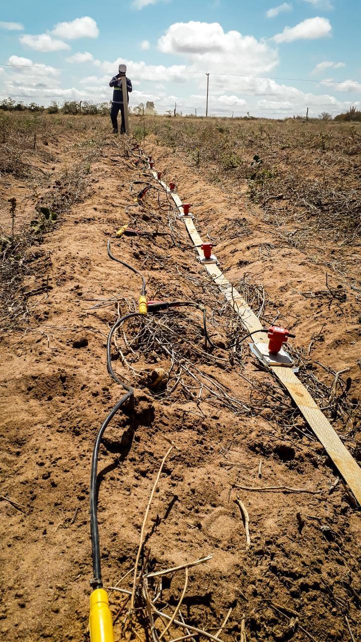
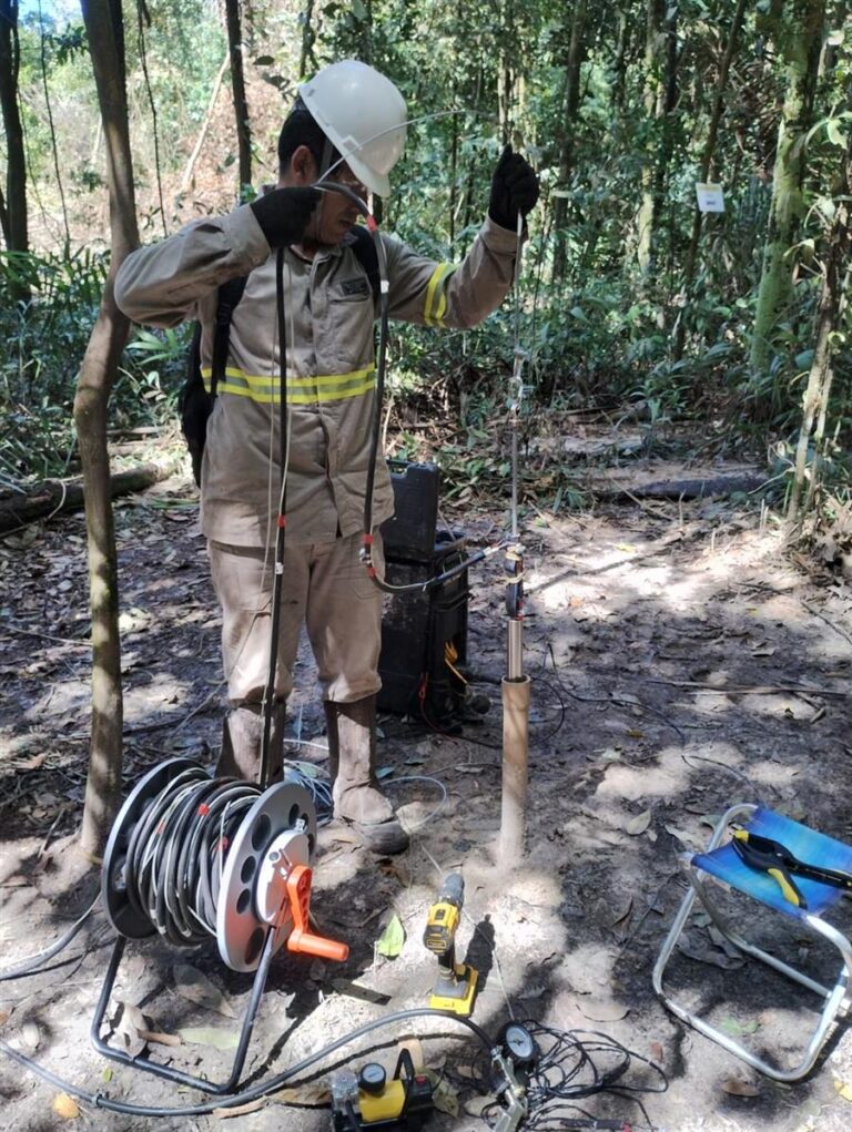
- Field measurement methods, such as the Wenner array
- The layout and number of measurement points according to the site area
- Data processing and the construction of a layered soil model, with the resistivity and thickness of each layer, which feeds the grid calculation
The layered model is the key output. A single resistivity value rarely represents the ground adequately.
What about NBR 15749?
NBR 15749 covers grounding resistance measurement and surface potentials. It applies once the system is installed, to check that performance matches the design. One of the methods used is fall-of-potential, carried out with an earth resistance tester.
The two standards work together: NBR 7117-1 feeds the design and NBR 15749 verifies the result.
Where geophysics helps
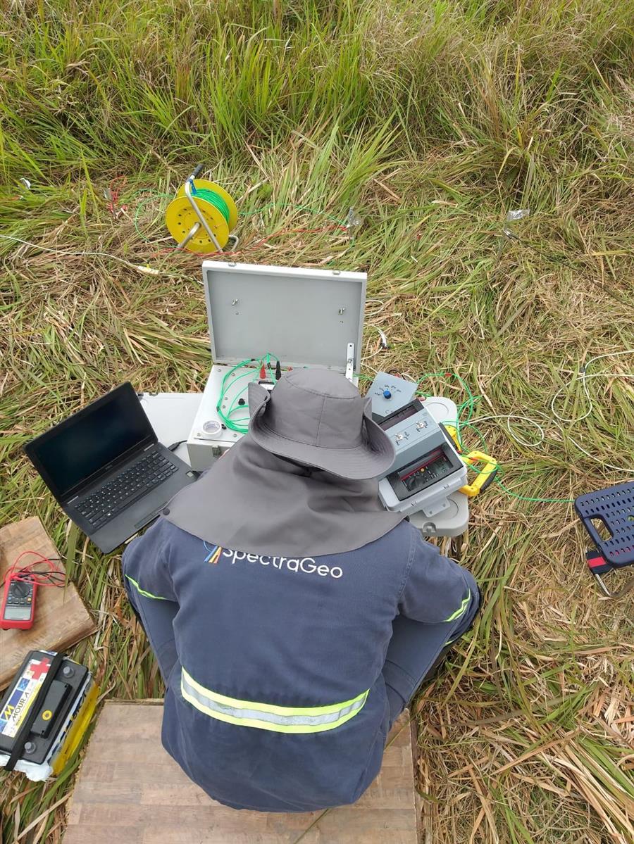
Beyond the measurements required by the standard, geophysical electrical methods give a broader view of the ground:
- Vertical Electrical Sounding (VES): details how resistivity changes with depth at a point.
- Electrical profiling: shows lateral variation along sections and highlights contacts, wet zones, faults and cavities that may affect the grid or the foundations.
On linear projects such as transmission lines, or large sites such as substations and wind and solar farms, this continuous view helps identify where the ground changes and where more measurement points are needed.
Summary
- Soil resistivity is the basis of grounding design.
- NBR 7117-1 guides measurement and layered modeling.
- NBR 15749 guides verification of the installed system.
- VES and electrical profiling extend characterization across large or heterogeneous sites.
Need resistivity measurements for a grounding design? Talk to our team.